The JustBases advice journal
What is the best foundation for a telescope pier?
Compare isolated concrete pier foundations, existing slabs and alternative supports, with advice on vibration, mount height, anchors and future upgrades.
By JustBases 10 min read
Explore the installation service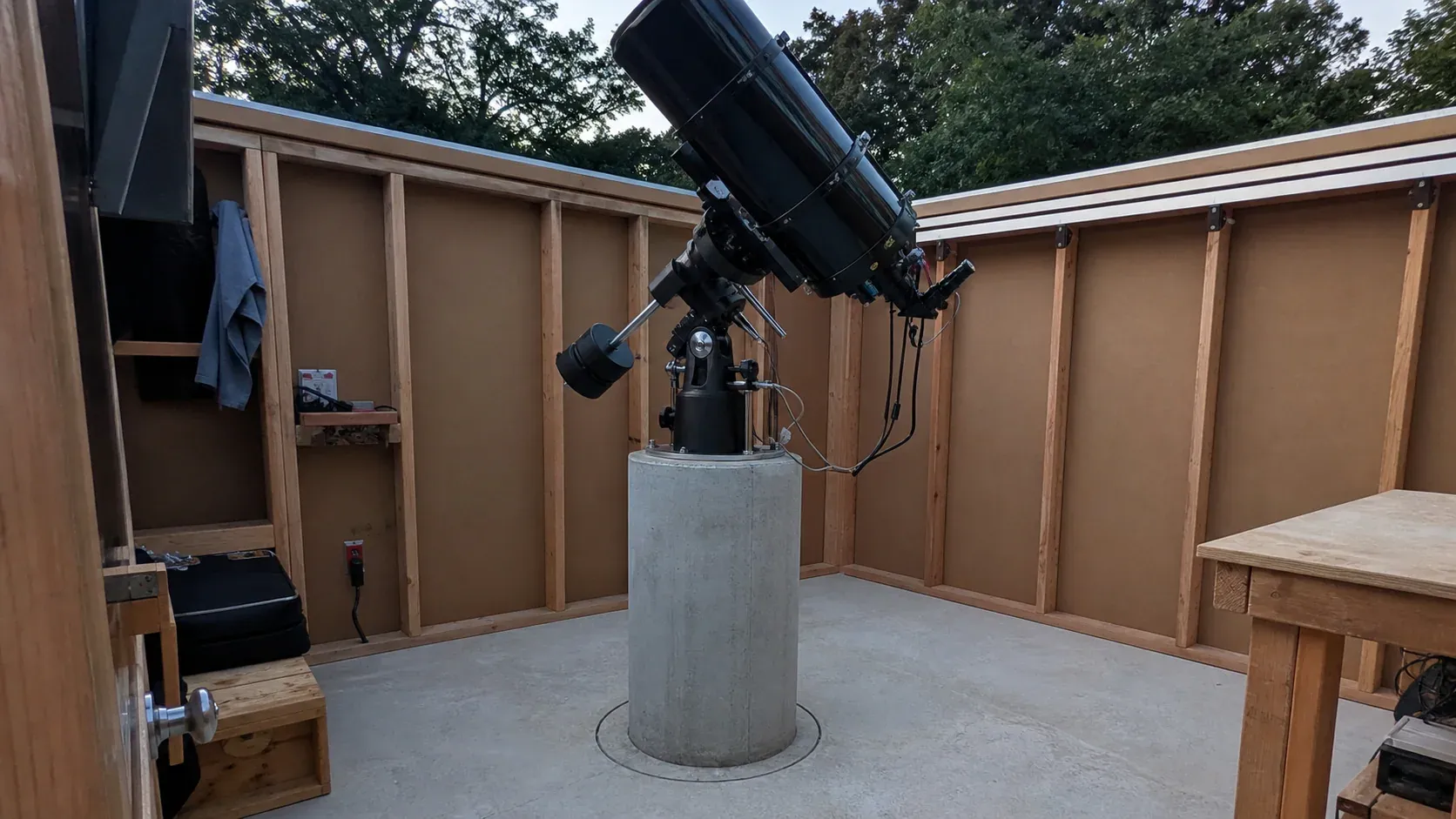
In this article
For a permanent telescope pier, an appropriately designed isolated concrete foundation is usually the best starting point. It provides a dedicated support for the mount while keeping footsteps and observatory movement out of the direct structural connection. The dimensions and anchor arrangement must suit the telescope, pier, ground and required performance; there is no universal hole size that works for every observatory.
Ground screws may be excellent beneath the surrounding observatory enclosure, but an ordinary screw-supported frame is not an interchangeable precision-pier foundation. Our telescope pier foundation service constructs the approved concrete support, with the bolt template, height and isolation detail coordinated before pouring.
Why stiffness matters more than standing weight
A telescope mount can weigh much less than equipment commonly placed on an industrial slab, yet be far more sensitive to tiny movements. Long exposures and high magnification make the support’s behaviour important even when there is no concern about the structure carrying the weight.
The foundation should keep the pier stable, while the pier and mount provide the geometry intended by their designers. A large block beneath a flexible connection does not automatically create a stiff system. The whole path from ground to telescope matters.
Eagle Rock Observatory’s construction record separates the pier foundation from the observatory floor and foundation. That is useful evidence for the isolation principle, not a set of dimensions to transfer to another site.
Start by describing the equipment and observing aim. Visual observing, planetary work and long-exposure imaging may create different expectations. The designer can then establish the support appropriate to the actual use rather than sizing it from a generic internet rule.
The realistic support options
| Arrangement | Benefits | Limitations |
|---|---|---|
| Isolated concrete block with steel pier | Dedicated support and replaceable above-ground pier | Anchor accuracy, pier stiffness and ground design remain important |
| Concrete foundation and concrete pier | Continuous structural form where designed | Less flexibility for later height or mount changes |
| Assessed existing slab | Avoids new construction for a suitable use | Building vibration, joints and unknown support may limit precision |
| Tripod on a stable observing surface | Flexible and removable for occasional use | Repeated setup and sensitivity to the surface remain |
| Specialist engineered alternative | May address unusual ground or equipment needs | Requires performance design; ordinary garden supports are not equivalent |
Isolated concrete block and steel pier
A concrete foundation supporting a purpose-made steel pier is a common practical arrangement. The buried support provides a stable base, while the steel pier connects to the mount through the approved top adapter.
One advantage is adaptability. The above-ground pier or adapter may be replaceable if equipment changes, provided the new arrangement remains compatible with the foundation and anchors. That can be more manageable than altering a concrete column.
The foundation should be designed for the ground and performance requirement. Its dimensions cannot be inferred only from the telescope’s weight. Nearby disturbance, the pier height and the stiffness of the complete connection can influence the outcome.
The anchor template is a critical interface. The pier supplier should provide the correct pattern and orientation, including any intended levelling arrangement. Set it from the current drawing and check it before the pour, rather than trying to correct a mismatch with enlarged holes later.
Concrete placement and pier installation need a coordinated programme. Agree when the foundation is ready for anchors and equipment, and protect the template during construction so it is not disturbed before the concrete has developed the required condition.
Concrete piers
A concrete pier can form part of a purpose-designed observatory support. It may offer a direct structural arrangement and can be appropriate where the height and equipment are well established.
The trade-off is reduced flexibility. Changing height, top geometry or the mount interface later can be more involved than replacing a steel pier or adapter. Plan the telescope’s parked position and required clearances before committing to the final form.
ScopeDome’s tower-type observatory detail illustrates a designed relationship between pier, foundation and surrounding structure. It is a particular engineered system, not a general-purpose concrete specification for a domestic observatory.
As with a steel pier, the surrounding floor should not touch the telescope support where isolation is required. A continuous concrete material does not mean everything should be poured as one connected structure.
If cables are to pass through the pier or foundation, the route must be agreed before construction. The conduit should not conflict with reinforcement, anchors or the intended mount connection.
Why a shared observatory slab can disappoint
A continuous slab supporting both the pier and the occupied room seems simple and substantial. Its limitation is that footsteps, doors and roof movement can have a direct structural route to the telescope.
That may be incompatible with the intended imaging performance even though the slab is structurally strong. A foundation can be safe under the load yet unsuitable for the precision task.
Where isolation is required, design a separate pier block and maintain the specified gap around it. Do not bridge that gap with grout, rigid trim, floor finishes or stored material. The detail needs to remain effective after the observatory is finished, not merely during the first inspection.
An existing slab may still be usable for some observing arrangements after assessment. Be clear about the performance you expect and what compromises you are willing to accept. Reusing a surface for a portable tripod is a different proposition from promising a permanent imaging foundation.
Ground screws belong in the right part of the observatory
We prefer ground screw foundations for compatible framed observatory buildings where they reduce concrete and ground disturbance. A timber-frame base on screws can support the room while the telescope stands independently on its concrete pier foundation.
That mixed arrangement can be a sensible use of materials. Concrete is concentrated where precision support calls for it, while the enclosure does not automatically require a full slab.
An ordinary screw-supported deck should not be presented as a guaranteed telescope-pier alternative. Its stiffness, connections and ground interaction would need specialist assessment for the required performance. Capacity to support a person or building is not proof that it will satisfy an imaging mount.
If a specialist supplier proposes a different pier foundation, ask for the design and acceptance criteria. There may be appropriate engineered solutions for particular sites, but those should be evaluated on their actual evidence rather than the appeal of avoiding concrete.
Steel, timber, concrete, excavation and transport all have impacts. The environmentally responsible approach is the suitable complete design, with unnecessary material avoided and future changes considered.
Get the height and orientation right
The foundation’s finished level, steel pier height and mount adapter combine to establish the telescope position. Check all three together with the enclosure and roof geometry.
A pier that is too high may create roof-clearance problems; one too low may limit views over the walls or make observing awkward. The correct answer depends on the telescope, mount and intended use rather than a standard comfortable height.
Confirm the mount’s orientation requirements before fixing the bolt template. Polar alignment needs and the available adjustment range should be understood by the astronomy equipment team. The groundwork should provide the approved starting geometry.
Consider the telescope in its parked and operating positions, including cameras, focusers and other accessories. A tube that fits without accessories may not clear the closed roof once the complete imaging train is attached.
If the mount changes before installation, revisit the drawing. Similar-looking piers and adapters may use different patterns. It is better to delay a pour briefly than permanently cast the wrong interface.
Ground conditions and nearby movement
The designer should consider what lies beneath the pier, not only the visible lawn. Filled ground, former trenches or nearby structures may affect the support arrangement.
Do not copy a foundation depth from an observatory in a different climate or soil. Online build accounts are useful for ideas and lessons, but their dimensions are not evidence that the same design suits your garden.
Tell the team about known drains, cables, former building footprints and any ground movement you have observed. That information can guide the appropriate assessment. It does not mean you need to carry out a survey before the first conversation.
Nearby vibration sources also matter to the intended performance. A foundation cannot guarantee immunity from every source of ground movement. If the observing goal is particularly demanding, discuss that explicitly with the specialist rather than assuming more concrete always solves it.
Cable routes without vibration bridges
Power and data are easy to overlook when concentrating on the pier itself. Plan where cables will enter, how they reach the mount and how they can be changed later.
Rigid conduits or tightly restrained cables can create unwanted connections between structures intended to remain separate. The designer should specify an appropriate route and flexible detail where needed.
Keep cable openings clear of anchors and levelling hardware. A convenient conduit position at foundation stage may become awkward once the pier’s bottom plate is fitted. Review the complete assembly before pouring.
Photographs and an as-built sketch are useful when the floor later hides the routes. Leave access that suits future equipment changes rather than sealing everything permanently around the first telescope configuration.
Electrical installation and any bonding or earthing belong with the competent specialist. The foundation contractor should follow the agreed provisions without treating structural steel or reinforcement as an electrical design by default.
The surrounding floor and maintenance space
The floor should let you move comfortably around the pier without contacting the telescope support. Avoid placing cupboards or fixed furniture so close that routine work becomes awkward.
The isolation opening needs a practical finish. It should preserve separation without leaving an unnecessary snag point for cables or footwear. Use the observatory designer’s detail rather than filling the gap with whatever material is available.
Drainage and moisture protection around the enclosure also matter. Water should not be directed towards the pier opening, and the building’s ventilation strategy should remain effective after the floor is finished.
If the pier is outdoors without an enclosure, the equipment supplier should define the weather protection and connection details. A permanent foundation does not make the mount or its electronics suitable for unrestricted exposure.
Compare foundation quotations by their interfaces
A useful quote identifies the pier and mount, foundation drawing, top level, bolt template and isolation arrangement. It should include excavation, spoil handling, concrete construction, ducts and any surrounding reinstatement.
Clarify who supplies the template, verifies orientation and installs the steel pier. Agree who handles grouting or final levelling where the design requires them. Telescope assembly and alignment should remain with the astronomer or equipment specialist.
For an observatory project, compare the pier foundation together with the enclosure base so neither contractor assumes the other is preserving the isolation gap. The two scopes should meet cleanly without being structurally joined by accident.
Contact JustBases for a telescope-pier foundation quotation with your mount, enclosure idea and site photos. We can begin the discussion while you refine the equipment, then build the approved detail once the critical geometry is settled.
Frequently asked questions
How deep should a telescope pier foundation be?
There is no universal depth. The ground, pier, equipment and required performance determine the design. Use the supplier or engineer’s detail rather than dimensions copied from a different observatory.
Can the pier be bolted to the observatory floor?
Where vibration isolation is required, the pier should have a separate foundation rather than relying on the occupied floor. An existing slab may suit some less demanding arrangements after assessment, but that is a different performance choice.
Can ground screws support the observatory around the pier?
Yes, where the enclosure and frame are suitable. This can reduce concrete while leaving the telescope on its own appropriately designed isolated foundation.
Can I change telescope mounts later?
Possibly, using an approved compatible pier or adapter. Consider likely changes early, but check the new height, load and connection rather than assuming the original foundation suits every future setup.
More advice for your project
What is the best base for a garden observatory?
Compare ground screws, timber floors and concrete observatory bases, with advice on isolated telescope piers, roof tracks, drainage and cable routes.
What is the best foundation for a lathe or milling machine?
Compare existing workshop slabs, dedicated concrete pads and isolated foundations for lathes and mills, including alignment, anchors and delivery planning.
What is the best foundation for a memorial or headstone?
Understand memorial foundation slabs, ground anchors and monolith systems, with respectful advice on cemetery approval, stability and long-term care.